Defining Levels: To follow along with this example run the
network builder by executing the command isip_network_builder at
the command prompt. Then follow the proceeding steps.
|
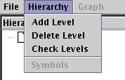
Step 1: In the main panel, click Hierarchy and select Add Level.
|
|
|
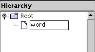
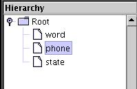
Step 2: A new level appears underneath "Root" in the Hierarchy
window. Single click this and wait for the color to change to
white and a blinking cursor to appear. Change the name from
"New Level" to "word" and press enter.
|
|
|
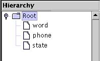
Step 3: Repeat these steps, adding a level named "phone" and
then a level named "state". Make sure to add the "phone"
level first and then the "state" level.
|
|
Add Nodes: Placing the nodes is done as follows.
|
Step 1: In the main panel, click Graph and select Insert Start.
|

|

|
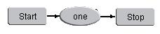
Step 2: Move your cursor to the rightmost panel. You'll notice the
pointer has changed from an arrow to a pointing hand. Click on an
area and a box labeled Start will appear. Click Graph again
and this time select Insert Stop. Place this in the same panel. Every
network diagram needs a Start and a Stop node.
|
|
Step 3: Click Graph again and select Insert Node. Click
on the right panel to place this node.
|

|

|
Step 4: Right click the node you just entered to bring up the
configuration menu. In the Node Name box, enter "one". Enter
"one" in the textbox in the lower lefthand corner and click
Add. Then click OK.
|
Defining Paths: Follow these steps to connect a path between nodes.
|
Step 1: In the right panel, click the Start node and then click the
node labeled "one". A line will be drawn with an arrow pointing
towards the "one" node. Next click the "one" node and click the Stop
node to draw another line.
|
|

|
Step 2: Although we aren't using it here, it is possible to
draw a line tracing a path from a node to itself by clicking once
on the node and then clicking that same node again.
|
Repeating the Process: Now that the nodes have been defined for the
word level, what remains is to fill in the nodes for the phone and state
levels. The steps to do this are listed below
|
Step 1: In the Hierarchy panel, click on the level that was named
"phone" earlier.
|
|
|
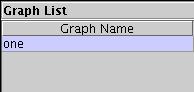
Step 2: The panel on the right now becomes blank. In the Graph List
panel, there is an entry labeled "one". This entry is from when we
added the symbol "one" to the node named "one" earlier. Click this
word to make sure it is selected.
|
|
Step 3: Using the same process as before, enter the graph shown to the
right for this entry. Make sure to right click each node you enter
and to change the name accordingly and add a symbol with the
same name to the list.
|
|
|
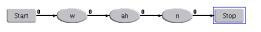
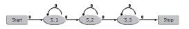
Step 4: Now click the state level on the Hierarchy panel. Under the
graph list, there are now three entries : w, ah, and n. The
image to the left shows the graphs for the ah phone.
The graphs for the w and n phones are identical to the sil
phone, only the labels are different for the nodes. Enter in different
labels for these nodes in the form S_N where N is a
sequence of numbers.
|
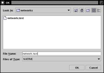
Step 5: Finally, to save your practice work, click File in
the menu and choose Save. Go to the directory:
$ISIP_TUTORIAL/sections/s06/s06_02_p03/
Choose a name for your file and enter
it in the File Name text box. You can save your file as one of three
formats: a NATIVE (.text) file, a DIGRAPH (.sof) file, or a JSGF (.sof)
file by click the drop down bar next to Files of Type. When you have
entered a file name and chosen your file type, click OK.
The resulting file for this excercise can be compared to the file in the
following directory:
$ISIP_TUTORIAL/sections/s06/s06_02_p03/compare/
|
|
Defining Symbol Types: Below are definitions for some of the commonly
used symbol types.
The image to the right shows the list of symbol types. These types
tell the recognizer how to treat each symbol and the symbol's role
in the language model. Definitions for some of the more common
types are below.
non-speech - symbol does not correspond to speech. This symbol
is mainly used for silence models.
context-less - when using context-dependent grammar, any symbol
with this attribute cannot be the central context
dummy - a dummy symbol contains no graph and is used as a
break node between two arcs. If a symbol contains a graph and is
defined as a dummy node, the graph will be deleted once the
network is saved.
exclude - an exclude symbol has no transcription. Usually,
silence and delimiter symbols are defined as exclude symbols.
attach-statistical - if the 'Save All' feature is used,
a hash table containing all 'attach-statistical' symbols will
be created.
|

|
|


